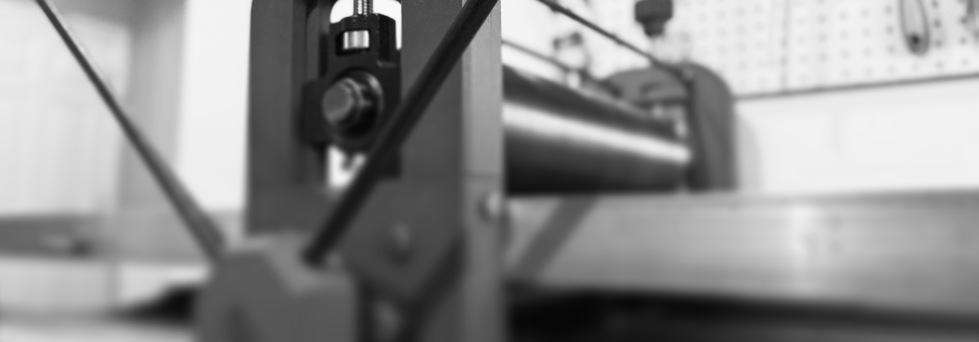
Brockway 250 Printing Press
A New Era for Artists
For centuries, printmakers have dreamt of standing at the helm of a printing press, the scent of ink in the air, the wheel’s steady turn leaving streams of art glistening in its wake.
Yet traditional presses, as grand and poetic as they are, often cost several thousand dollars, leaving many artists’ dreams out of reach.
I refused to let this hinder me. By fusing tradition, 3D printing, and AI, I designed and built the Brockway 250: a sturdy, modular, 19″ lino and woodcut press.
I’m thrilled to share its plans for free, inviting you, artists and makers, to steer your own artistic voyage.
Get the Free Designs
In the spirit of open source, I’m giving these designs away for free. Continue here to get the free design files and instructions:
Why 3D Printing?
The Calling
I should clarify that I didn’t set out to create a “3D-printed printing press”. This wasn’t a hammer looking for a nail, as can often be the case in 3D printing.
A cursory web search led me to a number of existing homemade presses, namely one by Javier Lopez, which proved to me that an affordable, home-made press for linocut/woodcut was achievable. I’ve based my plans heavily off of Javier’s plans, who based his off of other plans before him, and so goes the lineage, perhaps all the way back to Gutenberg.
But with these plans, I was intimidated by the amount of precise metal machining involved, the hefty weight of a pure metal press, the cost (still higher than I’d have liked), and personally, Brutalism wasn’t the vibe I hoped for. I was hoping something more Art Deco, Gothic, or even eventually Baroque.
Traditional Machine, Modern Approach
So after getting my feet wet with 3D printing at my local library’s makerspace, I became wide-eyed about the profound possibilities of 3D printing. This tool solved all of my concerns, and unlocked even more possibilities for a press design:
- Affordability
Rather than buy a $150 aluminum roller, I could just print one for $30 worth of filament. If I needed bolts, nuts, or bearings, I could just print those. - Modularity
I could update specific components over time. If something broke, I could just reprint it with stronger print settings. I could create custom add-ons with ease. - Iteration
I could easily iterate on specific components, and easily create new components with absolute precision. - Customization
Stylistically, I could imbue it with gothic or baroque inlays if I wanted. Make it art deco. Change the colors. With 3D printing, the possibilities are limitless. - Shareable
I love open-source for many things, and I’d be able to share the exact plans with makers and artists around the world. One day, if I came up with an improved version, I’d be able to share the new files almost as easily as an iPhone receives updates.
But for linocut and woodcut, would 3D printing be strong enough?


Strength Concerns
I was skeptical at first. But after doing some digging on the filaments available, and the strength needs of linocut and woodcut presses, I felt confident enough to give this project a shot.
There were a wide variety of filament options available for purposes like this, built for high strength, durability, rigidity, and different environmental conditions. And it’s evolving fast – seems like every week I get another email announcing a new high strength filament that’s available.
Furthermore, I wasn’t designing this to be an etching press, rather a printing press for linocut and woodcut. Those printing methods have totally different strength needs. So the strength needs of linocut and woodcut seemed totally reasonable and within range for a press like this.
Now, the only question was how to do it.
Design Process
Sketches & Prototypes
I always start with rapid sketches for my work. It helps me collect momentum. And I can quickly sift the good ideas from the bad ones, and identify the key steps to move forward.


From there, I modeled the ideas into dozens of prototypes in Fusion360, iterating feverishly, learning as I went. Each sketch and prototype was an experiment that brought me closer to the ideal form.


A few key design challenges arose from this process:
- Hub and Hub Joint
Due to the small size of the printing bed, the Hub that ties everything together would need to be printed in two parts. They’d somehow need to be joined in a way that’s enough to hold up under immense pressure. - Roller Design
How would I balance strength with price effectiveness? What was the minimum amount of filament needed that provided the highest amount of strength? Each roller would also need to be printed in two parts, which proved helpful for the next design challenge. - Roller Attachment
How could I keep the rollers from spinning freely around the axle, without additional machining? The solution to this was a pressure collet that sits invisibly between the two roller halves. - Helm Wheel
For the center of the wheel that moves the bed, how would I secure the spokes to the axle? They were four heavy, 1/2″ by 2ft long steel rods. For this I had to rely on some machining, threading the rods and feeding them into slots with embedded square nuts.
Through many iterations (a lot of cheap blue PLA filament), I arrived confidently at the form factors, material choices, and printer settings that would meet my goals.
Now was time for the final print.
Printing
Material selection
While I like to use PLA for prototyping, for production I landed on two very different production materials:

A high performance engineering plastic. Essentially nylon and fiberglass. Engineered to deliver exceptional strength, durability, dimensional stability.
Used for every part except the rollers.

Perfect balance of affordability, durability, and toughness. I personally went with a subtype called PETG-HF Translucent, which gave it additional aesthetic properties.
Used for the rollers and decorative elements.
I’m in complete awe at the magnificence of PA6-GF. Its strength, its texture, and overall sense of quality. The second material, PETG-HF, is far more common, and if you’ve printed before you’re likely familiar with it.
Both materials come in a wide variety of colors, so you can get pretty creative in choosing the colors for your press. For my press, I wanted my press colors to reflect the plants and trees that often make up my artwork.
Print Settings
I’ve included the printer settings in the downloadable plans, so I won’t detail them too much here. But overall, the key factors to consider were:
- Speed
Slower printing speed creates stronger parts. Additionally, PA6-GF reallllly slow printing, no higher than ~50-60mm/s. Expect to spend days printing, nonstop. It’s worth it. The best things in life take time. - Supports & Brims
Use tree supports and brims (5mm) for everything, especially PA6-GF, to make sure models don’t lift off the bed. For tree supports, use a threshold angle of 30°. - Infill
For the sweet spot of strength and material usage, I found 20% 3D Honeycomb to work well. It’s an incredibly strong pattern, proven by the natural world and engineering best practices (the rocket engine and spinal implants above both use it, I believe). If you have the time and resources for a higher infill percentage, that would only help. - Wall Loops
Very important for strength. I found 5 walls (top, bottom, sides) to be the sweet spot here, give or take. Higher wall count is better, if you can afford it. - Temperature & Humidity
For printing with PA6-GF, temperature and climate control are immensely important.


Do your own research. Make sure you understand each materials’ needs thoroughly. Dry your filament. Run small test models. Get the right adhesive. Clean your nozzle. Maintain proper temperature, fan speeds, and humidity. Monitor with a Nest cam, webcam, or built-in printer cam. Catch errors early. When in doubt, pause the print.
This checklist becomes far more important when working with more esoteric materials like PA6-GF.
Small Hardware
For the small parts, such as screws, bolts, and small bearings, you have a choice. You can buy metal hardware, or you can print it (screws/nuts/washers, bearings, and a wide variety of collets). I’ve included sized printable models for much of the hardware in the design files, and a list in the next section. These will come in handy if you’re outside of the US and struggle to get access to non-metric sizes, or if you’re like me and just got tired of running to the hardware store.
I personally went with a combination of metal and printed hardware. I think the printed versions look better, and I want to see how the strength holds up over time, which I’m confident it will.

Finishing
To finish the components, you’ll want to peel and shave off the brims. Be careful doing so, because PA6-GF’s strength means that the edges can be quite sharp. If you’re one who likes to sand the surface of models, you might find these 3D-printed sanding blocks helpful as well.
Material Breakdown
I’ve put together a list of the materials needed for this project. All threaded items listed below use coarse threading (perhaps aside from the machine screws, which are pretty standard). Prices for each of these can vary quite a bit depending on the source, and whether you print it or buy it. So total project cost will vary depending on your choices. But it’s achievable for right around $300.
Part | Number Needed | 3D-Printable version included? |
|---|---|---|
| Flange Bearings UCFL205-16 | 2 | |
| Take-Up Bearings UCT205-16 | 2 | |
| Cold-Rolled Steel Rod 1″ x 3ft For bottom roller | 1 | |
| Cold-Rolled Steel Rod 1″ x 2ft For top roller | 1 | |
| Hex Bolt 7″ 5/8 For height adjusters | 2 | Yes |
| PA6-GF Filament | 2 kg | |
| PETG-HF | 2 kg | |
| PA6-GF Adhesive | 1 stick | |
| Square Nuts 3/8″ For hub joint assembly | 4 | Yes |
| Hex Nuts 3/8″ | 8 | Yes |
| Hex-Head Bolts 3/8″ x 2″ For frame, and hub joint assembly | 12 | Yes |
| Collets 5/8″ For height adjusters | 2 | |
| Hex-Head Bolts 5/8″ x 2″ For flange bearing mount | 4 | Yes |
| Cold-Rolled Steel Rods 1/2″ x 2′ For helm handles | 4 | |
| Cold-Rolled Steel Rods 3/8″ x 2′ For support rods | 4 | |
| Aluminum Flat Bars 2″ x 1/4″ x 4ft For frame | 2 | |
| Aluminum Angle Bar (type 6061) 1″ x 1/4″ x 4ft For frame | 2 | |
| Square Nuts 5/8″ For height adjusters | 2 | Yes |
| Square Nuts 1/2″ For helm handles | 4 | Yes |
| Machine Screw 4M x 25mm For helm lock | 1 | Yes, but not recommended |
| Square Machine Nut 4M For helm lock | 1 | Yes, but not recommended |
| Machine Screws M3 x 20mm For roller collets | 4 | |
| Square Machine Nuts M3 For roller collets | 4 | |
| Roller Bearings 3/8″ For bed support rods | 4 | Yes |
Assembly
Once all of the parts were printed, the real fun began. The following CAD videos demonstrate how the key parts all come together.
Hub Assembly
Roller Assembly
I don’t have the helm assembly detailed here, but hopefully it’s a straightforward enough to just drop in the nuts and screw everything together.
Finished Press


First Print: “Hello World”
My roots are in the programming world, where there’s a tradition to make the first block of code a helloWorld() function of some sort.
Well, I just happened to have a half-carved block of linoleum sitting around (for… 3 years now?) waiting for the right spark of inspiration to complete it.
I wasn’t too stoked about this piece before, and it’s far from my best work. But now, it’s taken on a whole new meaning. Here’s “Hello World.”

And because affordable homemade tools are the Topic of the Day, here’s the art drying rack I designed using cheap wire shelving and – you guessed it! – 3D printed parts. I’m seeing things like this for $200-300 on Blick. Crazy. The printer indeed pays for itself.

Curveballs
Every project has its hiccups, where you learn and move forward, and this one was no exception. Here are some key things I learned the hard way, so you don’t have to:
- Rod Metal
Always choose cold-rolled steel over hot-rolled for this project. The steel I ordered was hot-rolled, meaning that the surface was rougher, soft, and had an imprecise, wider circumference. This wider circumference required many wasted hours tapering down the diameter by about 1/32-1/16″, so that it would fit within the bearing mounts. If you’ve ever tried to machine down a metal rod without proper machining tools, it’s a sweaty, messy job, and you should wear a mask. - Online vs Local Metal Providers
I mistakenly paid a boatload (~$50) for shipping the metal, before realizing there was a metal provider within 10 miles of my house, who also cut metal exactly to size free of charge (which could have saved even more money). I could have saved $50-100 and a lot of headache if I went this route. - Printer Hygiene
This was a rookie mistake if there ever was one. Never print with wet filament! During the prototyping stage, I stepped away from my machine for a few days, left the PLA loaded in the nozzle, where it hydrated and expanded, creating a nasty clog. Silver lining, this taught me every detail of how my printer works, since I had to disassemble and reassemble the printer head multiple times. - Coarse vs Fine Threads
I accidentally threaded my 3/8″ rods with a fine thread die rather than coarse. Whoops! It ended up working ok, since I could just print some fine-threaded nylon nuts, but overall coarse threads are far better for 3D printing. Additional tip: When threading, don’t wear shoes you might wear in the house. The cut pieces end up everywhere, you will step on them, and it will hurt.
What’s next?
I already have a backlog of improvements, and plan to iterate on this once I’ve gotten more feedback. I also hope to provide add-ons and more customization options. If anyone in the DIY community wants to join me in improving this open-source project, even better.
Happy building. 👋
Follow this project
To follow along with this project, you can subscribe here. If you change your mind, you can unsubscribe with a single click. I promise to send updates sparingly, only when it might be helpful.
Licensing
In the spirit of being open source, I’m giving these designs away for free. This ensures others can improve on them, everything remains affordable, and that no one is limited from achieving their artistic goals.
Thus these designs are protected by CC BY-NC 4.0. This means you can distribute, remix, adapt, and build upon these designs – but not commercially.

Have more questions before getting started? In the middle of building?
Ask questions here and I’ll be happy to help.
Absolutely love the build and the write up! The “curveballs” section especially is a nice touch. I’ve added this page to my “to build” list 🙂
I’d be curious if there are any elements of the build you feel really clicked, things where you feel you got it just about perfect?
Great to hear, and thanks for asking. The hub assembly joint definitely felt like magic when I landed on the solution, since it solved so many problems at once.
Feel free to reach out personally if you have any questions once you start building, and have fun!
Have you considered making the plans a normal download link? I tried the checkout process multiple times on multiple computers and it always freezes.
Oof! Sorry to hear that. Shoot me an email at eric at ericwittke dot com and I’ll send you a download link.
For better or worse, I need to gate the download to keep evil bots from crashing my server, but also bc I want the press to be available as an item alongside other printmaking tools I plan to make and share in the future.
This is incredible! I’m so excited to try this build. Have you thought about designing presses for other applications? I know the strength aspect makes etching difficult, but maybe plate lithography?
Thank you so much for making this open source. I can’t even begin to image the effort this took to engineer. Making printing more accessible like this is such a service all of us makers.
So happy to hear this! I don’t know much about plate lithography but I am very curious about it. I think some other makers might provide some other DIY presses better suited for that already.
For now my focus will be making this press even better in various ways over time (Ive already made a new handy storage rack for the top I’ll release soon, separately).
If you have any questions, challenges, or feedback along the way please reach out and let me know.
curious – I have a bambu lab carbon x1 – any issues with the 4mm nozzle that comes with it or do I need to jump up to a 6mm?
That’s a really great question – Bambu’s nylon-fiber filament works with 0.4, 0.6, and 0.8, and they do recommend 0.6.
I personally used 4mm hardened steel for everything and didn’t encounter any issues or strength concerns. Just make sure you’re adequately drying out the filament and keeping the nozzle clean.
tried to print the main Hub piece (the big U) using exact filament as required. Bought it new, dried it for 12 or so hours prior. feels like it shrinks as it prints and pulls off the print plate. tried now a couple times and no luck – same issue. Im using a bambu lab x1 carbon. any ideas on what could be causing that issue?
Oh man, yea this filament can be frustrating. A few things:
1. Are you using the special glue for the filament? That’s absolutely necessary for this filament
2. Printing very slowly per the filament specs?
3. Using brims?
4. Is chamber staying the right temperature per the filament reqs?
1. maybe I missed and using the wrong one. I’ll check again.
2-4 yes
any chance you have bambu lab x1 .3mf files?